China Top DC MCCB for Solar: How to Choose? begins with a practical question: what must the breaker protect, and under which conditions? A DC MCCB For Solar is not simply an oversized switch. It must interrupt direct current safely, where the arc does not naturally cross zero. That difference matters on a rooftop, inside a combiner box, or beside a battery inverter.
Dr. John D. McDonald, a recognized power-system protection specialist, emphasizes, “Protection must match the system’s real fault conditions, not merely its rated voltage.” This principle deserves attention when comparing Chinese manufacturers. Check the maximum system voltage, continuous current, short-circuit rating, poles, polarity requirements, and operating temperature. Also verify whether the stated breaking capacity applies to DC service, not only AC service. A neat datasheet can still mislead.
Field experience adds another layer. Dust may settle on an outdoor enclosure. Cable temperatures can rise under strong summer sunlight. Frequent switching may expose weak mechanisms or poor contact materials. Therefore, selection should include IEC 60947-2 or applicable local certification, verified test reports, traceable production records, and clear after-sales support. Manufacturer reputation helps, but evidence matters more.
The cheapest choice is rarely the simplest choice. Yet a premium label does not guarantee correct coordination. Engineers should compare the MCCB with fuses, inverters, cables, and upstream protection. They should also review installation torque and maintenance access. This is where many guides become too confident. Real projects contain gaps, substitutions, and changing loads. A careful decision leaves room for verification before purchase and commissioning.
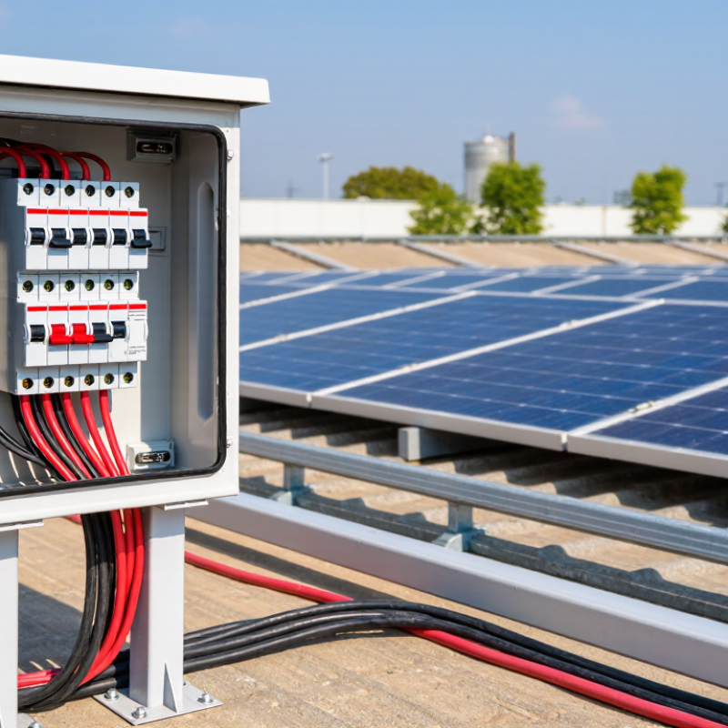
A DC MCCB, or molded-case circuit breaker, protects the direct-current side of a solar power system. It interrupts overloads and short circuits between photovoltaic strings, combiner boxes, batteries, and inverters. Unlike AC, DC does not naturally cross zero voltage. Arcs can continue after the contacts separate. That makes DC-specific arc control essential. It is not simply an AC breaker with a different label.
In practical system design, check the array’s maximum open-circuit voltage, including cold-weather correction. Compare it with the breaker’s rated DC voltage and pole configuration. Then calculate the continuous operating current from the array and confirm the interrupting capacity at the installation point. A breaker rated too low may fail during a serious fault. A rating too high may leave cables poorly protected. Cable size, ambient temperature, installation altitude, and coordination with fuses or inverter protection also deserve attention.
Field inspections often reveal a basic mistake: selection is based only on normal panel current. That approach feels convenient, but it can miss reverse current and unusual fault conditions. The enclosure should suit outdoor exposure, dust, moisture, and direct sunlight when installed near the array. Clear isolation labeling helps maintenance workers identify the correct circuit quickly. Small details matter. Even experienced designers should recheck calculations, because solar layouts change during installation and the final cable route may not match the original drawing.
When selecting a solar DC MCCB, electrical ratings deserve more attention than enclosure appearance. A neat cabinet cannot correct an undersized interrupter. Start with maximum system voltage, including cold-weather open-circuit voltage. The breaker’s DC voltage rating must meet or exceed that value for the actual pole arrangement. Do not transfer an AC rating to a DC circuit. DC arcs behave differently and can continue after contacts separate.
Rated current, In, should match the protected conductor and design current. Check temperature derating inside a roof-mounted enclosure; heat changes practical capacity. The interrupting rating, Icu and preferably Ics, must exceed the available DC fault current. For battery-backed systems, calculate battery contribution, not only PV short-circuit current. Poles, polarity, and series connections also matter. A two-pole device may require a specific connection to achieve its published voltage rating. This detail is easy to miss.
I also verify insulation voltage, Ui, impulse withstand voltage, Uimp, and suitable trip characteristics. These figures support insulation coordination during switching and surge events. In field checks, I compare the datasheet with cable size, combiner layout, and measured operating conditions. One imperfect habit is choosing the nearest current rating. It saves time, but it can weaken selectivity or cause nuisance trips under heat. Confirm test evidence against the relevant DC circuit-breaker requirements, such as IEC 60947-2, before installation.
Matching a DC MCCB with solar panels, inverters, and batteries requires more than comparing ampere ratings. Start with the highest possible DC voltage in the array, including cold-weather voltage rise. The breaker’s rated voltage must exceed this value. For current, use the panels’ maximum operating current and short-circuit current, then apply the installation standard and local derating rules. A breaker that fits on a warm test bench may perform differently inside a hot combiner box.
The inverter changes the calculation. Its DC input current, maximum PV voltage, and permitted overcurrent protection should guide the MCCB selection. Check polarity, isolation requirements, and the number of poles. DC arcs do not naturally cross zero, so the breaker must be specifically rated for DC switching. Battery circuits need extra care. Consider continuous discharge current, expected short-circuit current, cable capacity, and battery management limits. The MCCB should protect the cable without nuisance tripping during normal inverter startup.
Tips: Keep the breaker’s interrupting capacity above the available fault current. Leave room for future panel expansion. Use short, correctly sized conductors, and verify torque at every terminal.
In field work, I often see a breaker chosen only from the inverter’s rated power. That shortcut is risky. A 10 kW system can produce different currents at 400 V and 800 V. The same ampere value does not mean the same protection. I would confirm the panel datasheet, inverter manual, battery data, and local electrical code together. Coordination with upstream and downstream protection also matters. Sometimes the first selection looks perfect, but temperature, cable length, or battery fault current exposes a weakness. Recheck it.
How to Match a DC MCCB with Solar Panels, Inverters, and Batteries
This illustrative example compares continuous operating current, a 125% design current, and a practical MCCB rating for three DC circuits. The PV array is based on a 600 VDC system with a 32 A maximum operating current, the inverter DC input is rated at 125 A, and the battery circuit is rated at 200 A continuous current. The selected MCCB must also have a DC voltage rating equal to or higher than the system voltage, an interrupting rating greater than the available DC fault current, and a trip characteristic suitable for the circuit and installation conditions. Final sizing must follow the applicable electrical code and the equipment manufacturer’s instructions.
China Top DC MCCB for Solar: How to Choose?
Solar capacity expanded by about 407 GW in 2023, according to the IEA PVPS Trends 2024 report. More arrays mean more DC protection decisions. A suitable DC MCCB should interrupt the system’s maximum fault current, not only its normal operating current. Look for a verified DC voltage rating, correct polarity marking, and a tested arc-extinguishing chamber. Thermal-magnetic protection helps manage overloads and short circuits. Adjustable trip settings can improve coordination between combiner boxes, inverters, and battery circuits. However, adjustment is useful only when engineers calculate cable capacity and fault levels.
Safety depends on installation conditions too. IEC 60947-2 covers circuit-breaker performance, while IEC 60364-7-712 addresses photovoltaic installations. Check temperature derating inside hot enclosures. Confirm the breaker’s interrupting capacity at the actual DC voltage. Remote trip, auxiliary contacts, and clear isolation status can support emergency response and maintenance. Surge protection is also important, but it is a separate device, not a substitute for an MCCB. I have seen specifications focus heavily on ampere ratings. That can be misleading.
Tips: Compare tested DC data, not marketing language. Leave space for heat dissipation. Verify coordination with the inverter manufacturer’s protection study. Inspect terminals for loose connections during scheduled maintenance. Short circuits behave differently in DC systems. A familiar AC breaker may not be suitable. Mistakes happen. Every selection should be reviewed against local electrical rules and the project’s measured conditions.
| Selection Dimension | Typical DC Solar Requirement | Protection or Design Feature | Safety and Reliability Benefit | Practical Selection Guidance |
|---|---|---|---|---|
| Rated Operational Voltage (Ue) | Common photovoltaic distribution systems use 600 V DC, 800 V DC, 1,000 V DC, or 1,500 V DC architectures. | DC-rated insulation and switching capability at the actual system voltage. | Helps prevent insulation breakdown, excessive arcing, and unsafe interruption during faults. | Select a breaker with a DC voltage rating equal to or higher than the maximum open-circuit voltage of the PV array, including the lowest expected temperature. |
| Rated Current (In) | Selected according to the maximum continuous current of the string combiner, inverter input, battery connection, or DC distribution feeder. | Thermal current rating with an appropriate continuous-current margin. | Reduces nuisance tripping while limiting conductor and terminal overheating. | Verify conductor ampacity, enclosure temperature, grouping, installation method, and continuous-load requirements before final sizing. |
| Short-Circuit Breaking Capacity (Icu / Ics) | Must exceed the prospective short-circuit current available at the installation point. | High DC short-circuit interrupting capacity and, where specified, service breaking capacity. | Allows the MCCB to clear severe faults without catastrophic damage, fire escalation, or loss of the entire DC distribution section. | Use the calculated prospective fault current, not only the PV array operating current, when choosing breaking capacity. |
| DC Arc Extinguishing System | Required because DC current does not naturally pass through a zero-current point each cycle. | Purpose-designed arc chutes, magnetic blowout arrangements, adequate pole spacing, and DC switching geometry. | Shortens arc duration and limits contact erosion, thermal damage, and fire risk during disconnection. | Do not assume an AC MCCB has the same interruption performance on DC; confirm the manufacturer’s DC configuration and pole connection method. |
| Number of Poles and Pole Arrangement | Two-pole, three-pole, or four-pole arrangements may be used depending on system grounding and circuit topology. | All required live conductors are disconnected simultaneously when required by the design. | Improves isolation quality and reduces the possibility of backfeed or an energized conductor remaining in the circuit. | Match the pole arrangement to the PV system earthing method, inverter instructions, battery architecture, and local electrical code. |
| Overload Protection | Protects cables, busbars, terminals, and connected equipment from sustained overcurrent. | Thermal-magnetic or electronic long-time protection with adjustable current settings on applicable models. | Prevents progressive overheating and reduces insulation aging caused by prolonged overloads. | Set the long-time pickup below the permissible ampacity of the protected conductor while avoiding unnecessary trips during normal irradiance variation. |
| Instantaneous Short-Circuit Protection | Responds rapidly to high-current faults in DC feeders and combiner circuits. | Magnetic instantaneous trip or electronic short-time/instantaneous protection. | Limits let-through energy, arc-flash exposure, conductor damage, and mechanical stress on busbars. | Coordinate the instantaneous setting with downstream fuses, string protection, inverter input protection, and the available fault current. |
| Adjustable Trip Unit | Useful where current levels, cable sizes, inverter ratings, or system configurations vary. | Adjustable long-time, short-time, instantaneous, and sometimes ground-fault functions. | Supports selective coordination and allows settings to be adapted after load-flow and fault-current studies. | Choose adjustable protection for larger or expandable systems; lock and document final settings after commissioning. |
| Selective Coordination | Important for multi-level PV DC distribution with string, combiner, inverter, and main feeder protection. | Time-current coordination between upstream and downstream protective devices. | Allows the closest protective device to clear the fault, keeping unaffected PV sections in service. | Review time-current curves and energy let-through data rather than relying only on nominal current ratings. |
| Ground-Fault Protection | Applicable where the system design and applicable codes require detection of leakage or ground-fault current. | Ground-fault sensing, residual-current monitoring, or dedicated insulation-monitoring equipment, depending on system topology. | Helps identify insulation damage, accidental conductor-to-ground contact, and fire-producing leakage paths. | Confirm whether the inverter already provides ground-fault detection and ensure the MCCB function does not conflict with the system grounding scheme. |
| Isolation and Lockable Handle | Needed for maintenance, emergency shutdown, testing, and safe work procedures. | Clear OFF position, visible isolation indication, padlock provision, and suitable rotary or toggle mechanism. | Reduces the risk of accidental re-energization during inspection and repair. | Ensure the isolating function is suitable for the full DC voltage and that the handle position clearly indicates contact status. |
| Auxiliary and Alarm Contacts | Used in monitored solar plants, inverter control panels, battery systems, and remote operation centers. | Auxiliary contacts for ON/OFF status and alarm contacts for trip indication. | Enables remote diagnostics, faster fault response, event logging, and improved preventive maintenance. | Specify contact ratings, terminal arrangement, communication interface, and fail-safe signaling requirements. |
| Undervoltage and Shunt-Trip Accessories | Useful for emergency shutdown, fire-control interfaces, remote isolation, and interlocking. | Undervoltage release and/or shunt-trip release compatible with the control circuit. | Allows the DC circuit to be disconnected automatically or remotely under defined emergency conditions. | Check release coil voltage, operating time, control power reliability, and reset behavior before installation. |
| Temperature Performance | PV enclosures and combiner cabinets can experience high internal temperatures and continuous loading. | Temperature derating data, heat-resistant insulation, suitable terminals, and adequate ventilation or spacing. | Reduces nuisance tripping, contact resistance increase, terminal loosening, and thermal aging. | Apply the manufacturer’s current derating factors for ambient temperature, enclosure location, altitude, and adjacent devices. |
| Ingress Protection and Environmental Resistance | Outdoor solar equipment may be exposed to dust, rain, humidity, salt mist, ultraviolet radiation, and condensation. | Appropriate enclosure IP rating, corrosion-resistant materials, UV-resistant components, and moisture-control measures. | Protects insulation, trip mechanisms, terminals, and contacts from contamination and corrosion. | Evaluate the complete enclosure assembly, not only the MCCB body; outdoor installations often require additional sealing and anti-condensation measures. |
| Terminal and Cable Compatibility | PV circuits commonly use copper or aluminum conductors with different cross-sections and termination methods. | Correct terminal size, compatible lugs, approved conductor materials, and specified tightening torque. | Minimizes hot spots, loose connections, voltage drop, and fire risk at cable terminations. | Follow the approved lug type, cable preparation method, torque value, and periodic inspection requirements. |
| Insulation and Impulse Withstand | Outdoor PV systems can be exposed to switching transients and lightning-induced surges. | Suitable insulation coordination and rated impulse withstand voltage, used together with correctly selected surge protection devices. | Improves resistance to transient overvoltage and helps prevent flashover between poles or to earth. | Coordinate the MCCB insulation level with the system voltage, surge protective device, cable layout, and earthing arrangement. |
| Standards and Verification | Compliance requirements depend on the installation location, voltage level, and equipment application. | Testing and documentation to applicable low-voltage circuit-breaker and photovoltaic installation standards. | Provides verified performance for temperature rise, dielectric strength, endurance, and fault interruption. | Request test reports, datasheets, wiring diagrams, installation instructions, and traceable product documentation before approval. |
| Maintenance and Inspection | Periodic inspection is important because PV systems operate for long periods with variable environmental conditions. | Accessible terminals, testable trip functions, visual indicators, and documented maintenance procedures. | Identifies loose connections, insulation deterioration, corrosion, abnormal heating, and weakened trip performance early. | Include thermal scanning, torque verification, insulation checks, functional testing, and review of trip-event records in the maintenance plan. |
Important: Final MCCB selection must be based on the actual PV system voltage, maximum continuous current, prospective short-circuit current, conductor ampacity, grounding method, temperature, installation environment, and applicable electrical codes. Do not use nominal ratings alone.
China-based DC MCCB manufacturers should be compared through evidence, not catalogue appearance. IEA PVPS reported about 407 GW of new photovoltaic capacity in 2023. That growth increases demand for dependable DC protection. Start with the system voltage, continuous current, short-circuit level, and installation environment. Check rated insulation voltage, operational voltage, Icu, and Ics. For photovoltaic circuits, DC arc extinction is critical. An AC breaker is not automatically suitable for DC service.
Ask each manufacturer for IEC 60947-2 test reports, type-test certificates, and production traceability. Confirm whether the tested configuration matches the offered pole count and voltage. A laboratory report for one frame size may not cover every rating. This detail is often missed. Review temperature derating at 50°C or 60°C, because rooftop enclosures can become surprisingly hot. Check terminal capacity, creepage distance, polarity requirements, mechanical endurance, and protection coordination with fuses or inverters.
Factory quality deserves equal attention. Request calibration records, routine-test procedures, sample inspection data, and serial-number traceability. IRENA’s Renewable Capacity Statistics 2024 recorded solar as the largest source of new renewable capacity in 2023, reinforcing the need for repeatable supply quality. Ask about salt-mist testing for coastal projects and altitude corrections for remote sites. A lower quotation may hide weaker contacts or inconsistent trip performance. I would still inspect samples independently; supplier documents are useful, but they are not the whole truth.
It should handle overloads and short circuits in photovoltaic circuits. The interrupting rating must exceed the system’s maximum fault current. Normal operating current alone is not enough. That distinction matters.
DC arcs can continue after contacts separate. A suitable breaker needs tested arc-extinguishing performance at the actual voltage. An AC breaker is not automatically suitable for DC service. That mistake still happens.
Thermal-magnetic protection manages overloads and short circuits. Adjustable trips can coordinate combiner boxes, inverters, and battery circuits. Use adjustments only after checking cable capacity and fault levels. Settings are not guesses.
Check temperature derating inside rooftop or enclosed equipment. A dark enclosure can become surprisingly hot. Leave space around the breaker for heat dissipation. Also inspect terminals for loose connections during maintenance.
Remote trip functions can support emergency shutdown procedures. Auxiliary contacts can provide status signals to monitoring equipment. Clear isolation indicators help technicians identify an open circuit. Visibility helps.
Compare tested data, not catalogue appearance or marketing language. Request test reports, type-test certificates, and production traceability records. Confirm that testing covers the offered voltage, pole count, and frame size. One report may not cover everything.
Review insulation voltage, operating voltage, Icu, and Ics ratings. Check terminal capacity, creepage distance, polarity requirements, and mechanical endurance. Ask about derating at 50°C and 60°C. Small omissions matter.
Request calibration records, routine-test procedures, sample inspection data, and serial-number traceability. Ask about salt-mist testing for coastal installations. Check altitude corrections for remote projects. I would still inspect samples independently.
Choosing the right DC MCCB For Solar is essential for protecting photovoltaic systems from overloads, short circuits, and dangerous DC arc faults. A DC MCCB is designed to interrupt direct current safely, making it suitable for connections between solar panels, combiner boxes, inverters, batteries, and distribution equipment. When selecting one, users should carefully evaluate the rated voltage, continuous current, breaking capacity, pole configuration, and compatibility with the system’s maximum operating conditions. These ratings must match the solar array, inverter input, and battery bank rather than being selected only by nominal current.
A reliable solar DC MCCB should also offer adjustable protection, clear status indication, dependable arc-extinguishing performance, and stable operation under temperature and environmental changes. When comparing China-based manufacturers and products, buyers should review technical documentation, testing evidence, quality-control procedures, customization capabilities, warranty terms, and after-sales support. A thorough comparison helps ensure that the selected breaker provides safe isolation, long service life, and dependable protection throughout the solar power system.

AceReare