Choosing the right Electrical Mccb is a practical decision that affects safety, uptime, and maintenance costs. A suitable breaker must match the circuit’s voltage, current, fault level, and operating environment. Small differences matter. A workshop panel may face dust, heat, vibration, or frequent switching, while an office installation may demand quieter, simpler protection.
This guide presents 10 practical tips for evaluating an MCCB before purchase or installation. It covers rated current, breaking capacity, trip characteristics, pole configuration, installation space, and accessory requirements. It also considers coordination with upstream and downstream protective devices. Manufacturer datasheets should guide every decision, not assumptions based on appearance or price. A qualified electrical professional should verify the final selection against applicable standards and the site’s design documents.
Real installations often reveal overlooked details. A breaker may fit the panel but lack adequate terminal space. A rating may appear correct but fail to handle motor inrush or ambient temperature. Not every selection goes perfectly. Reviewing test records, inspection findings, and previous maintenance notes can expose these weaknesses early. The strongest choice balances technical performance, verified certification, long-term availability, and safe servicing. Look beyond the label. A reliable MCCB is not simply a higher-rated device; it is the right protective device for a defined electrical system.
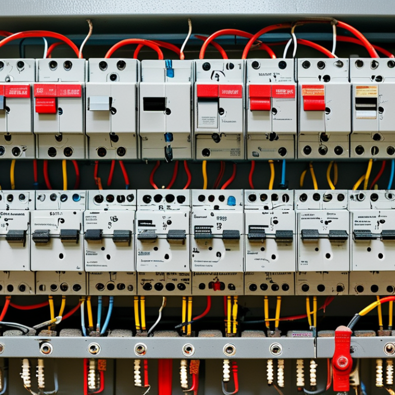
Choosing the right electrical MCCB begins with an accurate load assessment. Do not size it from the equipment nameplate alone. Record the system voltage, phase arrangement, frequency, and expected operating current. List motors, heaters, lighting circuits, and other connected loads separately. A motor may draw several times its running current during startup. That brief surge can cause nuisance tripping. Small details matter. Calculate demand using realistic operating conditions, not optimistic assumptions.
The MCCB must protect the conductors, equipment, and people from excessive current. Check the cable ampacity, installation method, ambient temperature, and enclosure conditions. Then compare the available fault current with the breaker’s interrupting capacity. This step is often rushed during small projects. It should not be. A breaker with the correct ampere rating may still be unsuitable for the system’s short-circuit level.
Review trip characteristics carefully. Adjustable thermal and magnetic settings can help match the actual load profile. Sensitive settings may trip during motor starting, while high settings can delay protection dangerously. Coordinate the MCCB with upstream and downstream protective devices, so one fault does not shut down an entire facility. Leave reasonable capacity for future expansion, but avoid excessive oversizing. I have found that early load estimates are sometimes wrong, so verified measurements and updated drawings deserve attention. A qualified engineer should confirm the final selection and test the installed settings.
Choosing the right electrical MCCB starts with matching its ratings to the installation, not selecting the largest frame size. Confirm the system voltage, frequency, grounding method, and number of poles. The MCCB voltage rating must meet or exceed the circuit voltage. A lower rating can compromise safe interruption.
Set the continuous current rating from the actual load, conductor capacity, ambient temperature, and enclosure conditions. Do not copy the cable label blindly. In panel reviews, I have found that heat from nearby devices reduced practical capacity. Allow suitable derating, especially inside crowded cabinets. The trip unit should protect conductors while tolerating normal motor starting currents.
Interrupting capacity deserves equal attention. Compare the MCCB’s short-circuit rating with the prospective fault current at its installation point. This value may differ between the main panel and a distant subpanel. Select an interrupting capacity equal to or higher than the calculated fault level. Standards such as IEC 60947-2 provide useful testing references, but project conditions still require verification. Check coordination with upstream and downstream protection, then review the manufacturer’s test data and installation instructions. I once treated a catalog rating as final. That assumption was too simple. Reliable selection depends on measured system data, updated fault calculations, and careful field inspection.
| No. | Selection Dimension | Recommended Check | Typical Reference Values | Practical Example |
|---|---|---|---|---|
| 1 | System Voltage | Select an MCCB with a rated operational voltage (Ue) equal to or higher than the system voltage. Confirm the required insulation voltage and frequency. | Common low-voltage systems include 230/400 V, 277/480 V, and 347/600 V AC at 50 or 60 Hz. Some devices are rated up to 690 V AC. | For a 400 V three-phase panel, choose an MCCB with Ue of at least 400 V AC and verify its rating at the actual frequency. |
| 2 | Continuous Current Rating | Choose a rated current that is not lower than the calculated continuous load current, while ensuring that cable ampacity and local code requirements are satisfied. | MCCB frame and trip ratings commonly range from approximately 16 A to 1,600 A, depending on the product family and application. | For a calculated design current of 248 A, a 250 A rating may be suitable only if conductor ampacity, ambient temperature, and installation conditions permit it. |
| 3 | Interrupting Capacity | The MCCB interrupting rating must be equal to or greater than the prospective short-circuit current at the installation point. | Common interrupting ratings include 10 kA, 18 kA, 25 kA, 36 kA, 50 kA, and 65 kA; higher ratings may be available for specific systems. | If the available fault current is 22 kA, select a device with an applicable interrupting rating of at least 22 kA at the system voltage. |
| 4 | Icu and Ics or Applicable SCCR | For IEC applications, check both ultimate short-circuit breaking capacity (Icu) and service short-circuit breaking capacity (Ics). For other standards, verify the applicable interrupting rating or short-circuit current rating. | Under IEC 60947-2, Ics may be specified as a percentage of Icu, such as 25%, 50%, 75%, or 100%, depending on the tested device. | For a critical feeder requiring repeated fault-clearing capability, prefer a device with a high Ics relative to its Icu, subject to the project specification. |
| 5 | Number of Poles | Match the pole configuration to the circuit arrangement and the required neutral switching method. Confirm whether the neutral pole is full-rated or reduced-rated. | Typical configurations are 2-pole, 3-pole, and 4-pole. Four-pole devices are commonly used for three-phase, four-wire systems when neutral isolation is required. | A three-phase, four-wire system with switched neutral requirements may use a 4-pole MCCB, subject to the grounding system and local electrical code. |
| 6 | Trip Unit and Protection Functions | Select thermal-magnetic or electronic trip protection according to the load, coordination requirements, measurement needs, and available adjustment ranges. | Electronic trip units may provide long-time, short-time, instantaneous, and ground-fault functions. Adjustment ranges vary by design. | A main distribution feeder may require adjustable long-time and short-time settings to coordinate with downstream breakers. |
| 7 | Load Type and Inrush Current | Consider motor starting current, transformer energization current, capacitor charging current, and other temporary inrush conditions to avoid nuisance tripping. | Motor starting current can commonly be several times the motor full-load current; the exact value depends on the motor and starting method. | A motor feeder may need an instantaneous pickup setting that allows normal starting while still providing effective short-circuit protection. |
| 8 | Temperature and Installation Derating | Check the manufacturer’s correction factors for ambient temperature, enclosure size, altitude, mounting position, and the number of adjacent energized devices. | Reference ambient temperatures are commonly around 40°C, but the applicable value depends on the device standard and product design. Altitude above approximately 2,000 m may require review. | An MCCB installed in a hot, compact enclosure may need a higher nominal rating or adjusted trip setting after thermal verification. |
| 9 | Coordination and Selectivity | Compare time-current curves and manufacturer coordination tables so that the downstream protective device operates before the upstream MCCB whenever practical. | Coordination depends on device settings, cable impedance, fault level, and tested combinations; it cannot be confirmed by current ratings alone. | For a distribution board, coordinate the feeder MCCB with downstream branch breakers to limit unnecessary shutdowns during a branch fault. |
| 10 | Standards, Accessories, and Installation | Verify the applicable standard, terminal arrangement, conductor size range, mounting method, enclosure compatibility, and required accessories. | IEC 60947-2 is widely used for low-voltage circuit-breakers. Common accessories include auxiliary contacts, alarm contacts, shunt trips, undervoltage releases, and motor operators. | A remotely controlled emergency-shutdown circuit may require a shunt trip, while a monitoring system may require auxiliary or alarm contacts. |
Selection note: Final MCCB selection should be verified against the applicable electrical code, the installation short-circuit study, conductor ampacity, enclosure conditions, and the device manufacturer’s certified technical data.
Choosing an MCCB starts with the trip curve, not the frame size. Thermal-magnetic trips suit straightforward feeders with predictable loads. Electronic trips offer adjustable long-time, short-time, instantaneous, and ground-fault functions. These settings must match cable ampacity, motor starting current, and available fault current. During commissioning, I have seen an instantaneous setting trip a healthy motor starter. The cause was ignored inrush.
NFPA’s Electrical Fires report recorded an annual average of 32,880 U.S. home fires involving electrical distribution and lighting equipment. The report used data from 2015 to 2019. Those fires caused about 470 deaths, 1,100 injuries, and 1.3 billion dollars in annual property damage. The figures do not prove MCCB failure. They show why protection coordination deserves measured attention. Use tested values, not optimistic assumptions.
Check selectivity between upstream and downstream breakers. An upstream trip during a small feeder fault can darken an entire production line. Review time-current curves at the actual prospective short-circuit current. For generators, transformers, and long cables, verify reduced fault levels and neutral protection. IEC 60947-2 defines performance requirements for low-voltage circuit-breakers, but it cannot choose your settings. That decision needs load studies, test data, and competent review. One setting can look correct on paper. Field conditions may disagree.
Choosing the right electrical MCCB starts with the installation environment, not the catalog rating. Measure the available space, enclosure temperature, humidity, dust, and expected altitude. A breaker installed inside a hot cabinet may carry less current than its nameplate suggests. Check conductor size, terminal access, bending space, and the required ingress protection. Small details matter.
Confirm the applicable electrical standard, such as IEC 60947-2, and verify local inspection requirements. Select the frame size, rated current, voltage, interrupting capacity, and number of poles together. The breaking capacity must exceed the prospective short-circuit current at the installation point. Calculate it. Do not rely on assumptions. Consider neutral switching where the system design requires it, and check whether adjustable protection settings need sealing or restricted access.
Coordination prevents one fault from shutting down an entire facility. Compare the MCCB with upstream breakers, downstream devices, transformers, and cable limits. Review overload, short-time, and instantaneous settings using actual time-current curves. Selectivity may be partial, not absolute. That distinction is often missed. Verify backup protection and energy withstand values before approval. A coordination study should reflect motor starting, transformer inrush, and future load growth. I have seen designs fail because the expected expansion was never included. Ask a qualified electrical engineer to review the calculations, test the installation, and document every setting. Keep the drawings current. Reality changes.
A practical review framework covering installation conditions, standards, protection settings, and coordination requirements.
The scores represent recommended engineering review priority on a 1–5 scale. Short-circuit rating, load current, installation conditions, and selectivity should be verified against the applicable design standards and the actual system study.
Reliability starts with correct application data. Check rated current, voltage, breaking capacity, and trip characteristics. Verify available fault current at the installation point. Select adjustable protection when load growth is likely. Review selectivity with upstream and downstream devices. A cheaper MCCB can still create expensive nuisance trips.
Uptime Institute’s 2024 Global Data Center Survey reported that more than half of respondents experienced an outage within three years. That finding makes coordination and tested protection more than paperwork. They directly affect operational continuity.
Maintenance costs deserve equal attention. Choose clear trip indicators, accessible terminals, replaceable accessories, and documented test procedures. Inspect connections for heat discoloration. Record trip events and operating cycles.
The U.S. Department of Energy’s Operations & Maintenance Best Practices Guide reports potential maintenance savings of 12–18% from preventive programs compared with reactive work. However, that figure is not guaranteed. Poor records can weaken even a good maintenance plan.
Include inspection labor, spare units, testing equipment, downtime, energy losses, and disposal costs in the ownership model. IEC 60947-2 compliance supports consistent performance, but certification alone does not prove suitability. Ask for test evidence, service life data, and coordination studies.
Reliability is built in the details. A useful comparison may reveal an uncomfortable result: the highest-rated device is not always the lowest-cost choice.
: Record voltage, phases, frequency, and expected operating current. List motors, heaters, lighting, and other loads separately. Motor starting current may briefly exceed running current several times. That surge can cause nuisance tripping. Small details matter. Use realistic operating conditions, not hopeful estimates.
Not by itself. Compare the load with cable ampacity, installation conditions, and enclosure temperature. The breaker must protect conductors and connected equipment. An oversized MCCB may delay protection during a fault. I would recheck early estimates because they are often wrong.
Determine the prospective fault current at the installation point. The MCCB interrupting capacity must exceed that value. A correct ampere rating does not guarantee fault suitability. Small projects sometimes rush this calculation. That is risky. Verify the result with qualified engineering review.
Check cabinet temperature, humidity, dust, altitude, and available space. A hot enclosure may reduce the breaker’s usable current. Confirm conductor size, terminal access, bending space, and enclosure protection. Measure the real cabinet conditions. Catalog values can mislead.
Adjustable thermal and magnetic settings can match actual load behavior. Sensitive settings may trip during motor starting. High settings may delay necessary protection. Review overload, short-time, and instantaneous settings together. Do not guess. Test the installed settings.
Coordination helps isolate one fault instead of shutting down an entire facility. Compare the MCCB with upstream devices, downstream devices, transformers, and cable limits. Review time-current curves using actual motor starting and transformer inrush conditions. Selectivity may be partial, not absolute. That difference matters. Keep drawings updated when the system changes.
Look for clear trip indicators, accessible terminals, replaceable accessories, and test procedures. Inspect connections for heat discoloration. Record trip events and operating cycles. Include labor, testing equipment, downtime, energy losses, and spare units. Good records matter. Without them, maintenance becomes guesswork.
No. A cheaper device may create repeated trips and costly downtime. A higher-rated device may also be unnecessarily expensive. Compare purchase cost, maintenance, testing, service life, and disposal. Certification supports consistency, but it does not prove application suitability. The uncomfortable answer may be the correct one.
Choosing the right Electrical Mccb begins with a clear understanding of the electrical load, operating voltage, expected current, and overall system requirements. Start by identifying normal and peak demand, possible overload conditions, and the available fault current. The MCCB’s voltage rating, continuous current rating, and interrupting capacity should match or exceed the system’s needs. It is also important to select suitable trip characteristics and protection functions, such as overload, short-circuit, and ground-fault protection, according to the equipment and application.
Installation conditions should also guide the selection. Consider ambient temperature, enclosure space, cable arrangements, environmental exposure, applicable standards, and coordination with upstream and downstream protective devices. Finally, evaluate reliability, ease of testing, maintenance access, replacement flexibility, and long-term operating costs rather than focusing only on the initial purchase price. A properly selected Electrical Mccb improves safety, reduces unnecessary interruptions, and supports dependable system performance over its service life.

AceReare