In heavy industrial electrical distribution, low-voltage Air Circuit Breakers (ACBs) serve as the ultimate defense mechanism for high-amperage installations. While the primary busbars handle current flow up to 6300A, the actual control, monitoring, and intelligent fault-handling mechanisms reside within the secondary control wiring diagram. For power systems engineers, switchgear builders, and industrial procurement managers, understanding this control matrix is imperative to secure electrical interlocking, remote automation, and precise protective tripping configurations.
An industrial ACB secondary circuit diagram is split into several interconnected loops: the motor charging circuit, the shunt trip circuit, the undervoltage release scheme, the auxiliary indicator contacts, and the intelligent controller unit (micro-processor trip units like LSIG). Each terminal designation must align with international standards such as IEC 60947-2 to guarantee absolute compatibility during switchgear assembly and commissioning.
This loop controls the automated mechanical energy storage. Upon energization (AC 220V/380V or DC 110V/220V), the internal gear motor automatically charges the closing spring. Once fully charged, the limit switch disconnects motor power, paving the way for remote closing commands.
Consists of the Shunt Trip (MX) for remote power interruption, Undervoltage Release (MN) for safety drops during power failures, and the Closing Coil (XF) to execute the remote breaker switch-on mechanism under interlocking safety boundaries.
Auxiliary contacts (usually 4NO/4NC up to 6NO/6NC) signal the circuit breaker's real-time positioning status to the external SCADA, control desks, or secondary PLC units. They reflect whether the breaker is connected, disconnected, open, or tripped.
Modern electrical installations are no longer confined to climate-controlled control rooms. As heavy industries shift to offshore wind, high-altitude desert solar farms, and Arctic mining regions, secondary control systems and breaker components must adapt. Acereare Group designs circuit breakers tailored for extreme conditions, leveraging over 20 years of manufacturing experience.
Operates down to -40°C. Using specific low-temperature greases and specialized heat-retentive wiring coatings, the electrical closing and tripping loops avoid mechanical freeze-ups.
Withstands coastal corrosion. The complete unit is tested for 72 hours (and sub-assemblies for 48 hours) to ensure secondary terminal contacts remain highly conductive in maritime systems.
For locations above 2000m. Due to thin air reducing dielectric strength, we apply engineering correction factors using altitude derating tables to guarantee control wiring integrity.
Provides precision measurement and remote diagnostics. Modbus, Profibus, or Ethernet communication links are wired to local panels to support digital substations.
Acereare Electric, founded in 2015, manages two wholly-owned manufacturing subsidiaries: "RuiRui Electric" and "KeRui Electric". Behind the registration lies a 20-year history of craftsmanship inherited across two generations, culminating in a robust manufacturing complex that ranks among China’s top-tier ODM and OEM power distribution component factories.
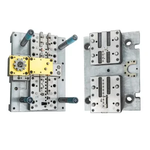
Operating with a comprehensive R&D structure, Acereare integrates raw material processing, mold design, stamping, assembly, and testing. This ensures that every MCCB, ACB, and secondary component complies with international quality standards.

From consultation and custom schematic design to shipping and local testing validation, we provide a unified supply chain solution.
Understand client parameters, current limits, and environmental specs.
Produce secondary wiring design and control layout files.
Finalize layout plans, electrical specifications, and contracts.
Integrate component manufacturing with ERP/MES monitoring.
Run quality tests in our laboratory for mechanical and electrical safety.
Pack with high-grade protective crating and dispatch globally.
Our plants utilize automated assembly lines alongside precision manual inspection stations. This hybrid approach ensures mechanical components match tight tolerances while control microchips are programmed, flashed, and tested against noise, voltage surges, and feedback loops.
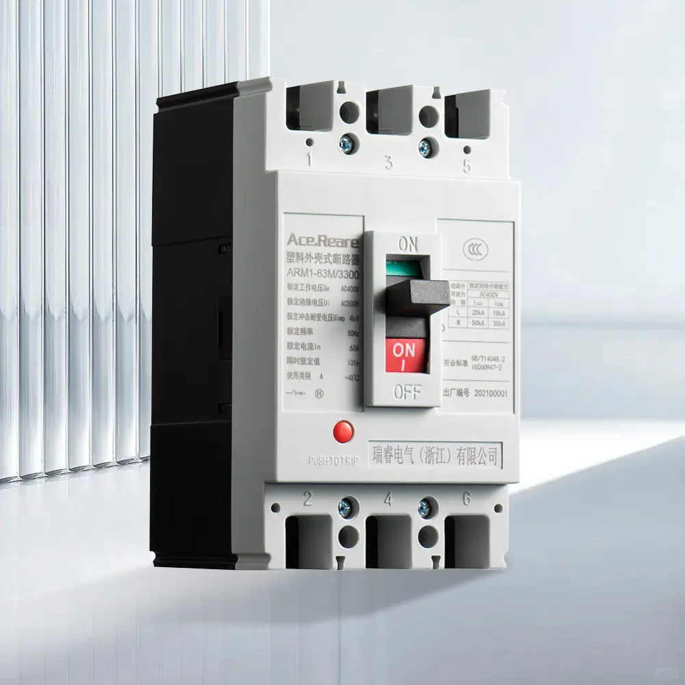
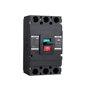
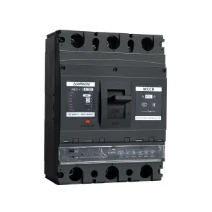
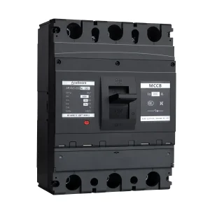
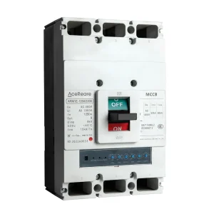
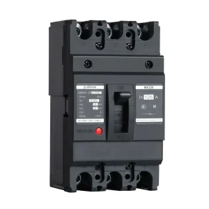
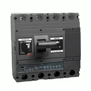
Standard thermal-magnetic Molded Case Circuit Breaker (MCCB).
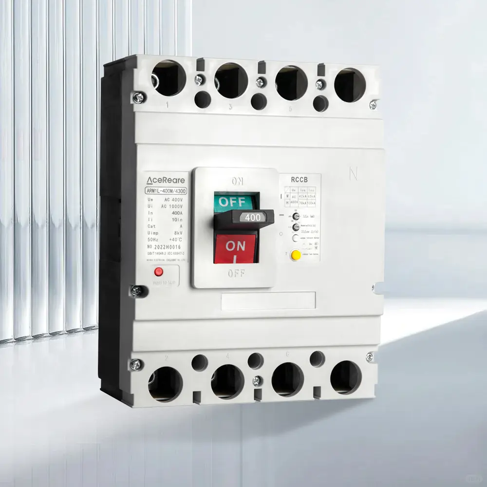
Residual current device with earth leakage fault protection.
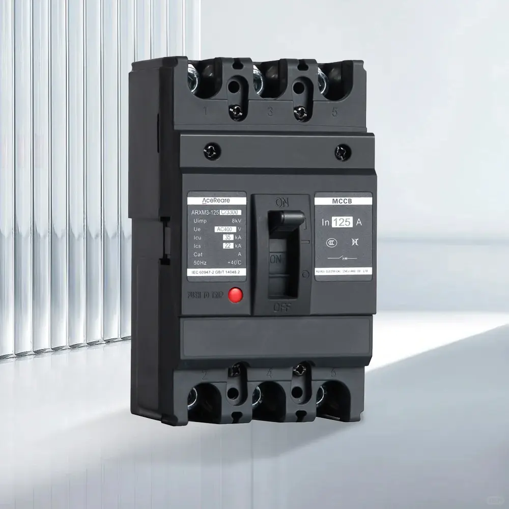
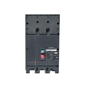
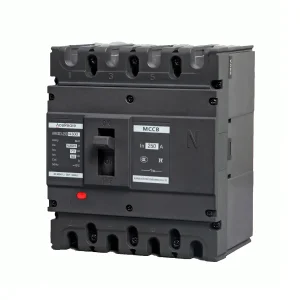
Thermal magnetic breaker for heavy-duty switchboard applications.
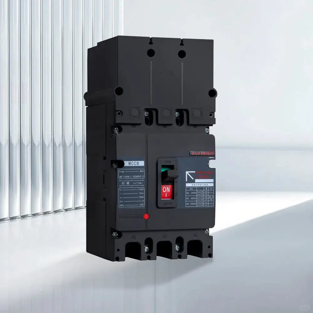
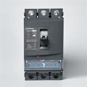
Electronic adjustable circuit breaker equipped with LSIG trip units.
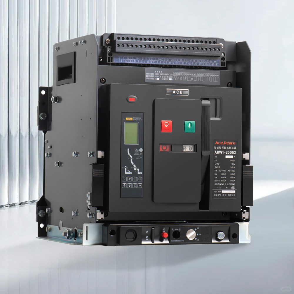
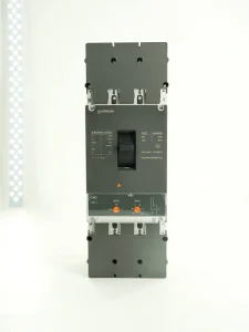
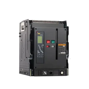
Intelligent Air Circuit Breaker, supporting 400A to 6300A configurations.
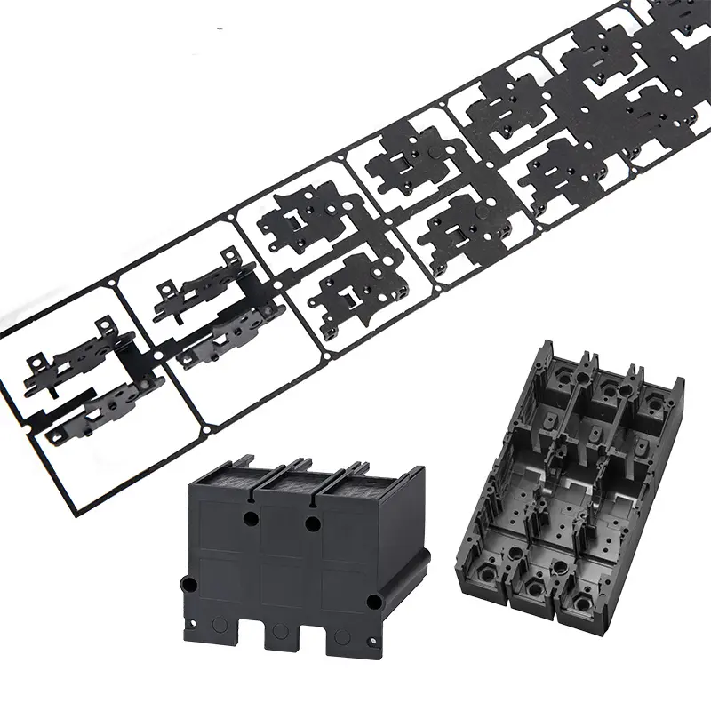
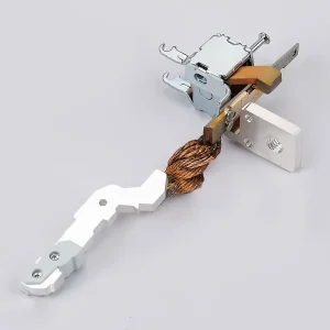
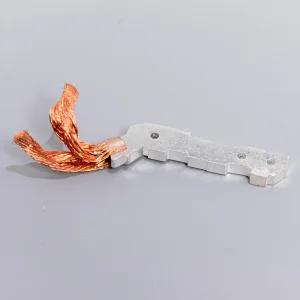
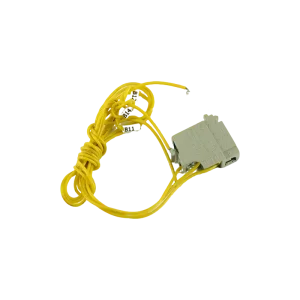
Moving silver contacts, coils, and terminal connections.
For project engineers, specifying an Air Circuit Breaker requires selecting the appropriate control wiring scheme. Dual-source automatic transfer switch (ATS) systems, mechanical interlocks, and electric release logic must be configured to prevent overlapping closed conditions.
| Terminal No. Range | Circuit Classification | Functional Pinout Purpose | Typical Rated Inputs Available |
|---|---|---|---|
| #1 - #2 | Motor Mechanism | Automatic motor spring charging loop (M) | AC 220V/380V, DC 110V/220V |
| #3 - #5 | Shunt Trip Coil (MX) | Receives PLC/SCADA commands for remote tripping | AC 230V, DC 220V, DC 24V |
| #6 - #8 | Closing Coil (XF) | Triggers spring release to close the main contacts | AC 220V, DC 110V |
| #9 - #12 | Undervoltage Release (MN) | Trips breaker if control voltage drops below threshold (35%-70%) | AC 400V, AC 230V |
| #13 - #24 | Auxiliary Contacts | Signals status indications (Open/Closed/Ready/Faulted) | 10A AC 380V / 0.5A DC 220V |
Standard thermal magnetic protection is insufficient for modern high-capacity power systems. Digital trip units integrate protective algorithms to monitor:
Our products are verified through third-party laboratories, complying with global standards.
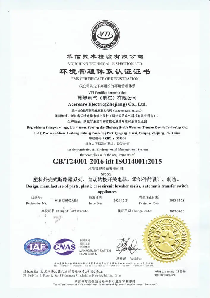

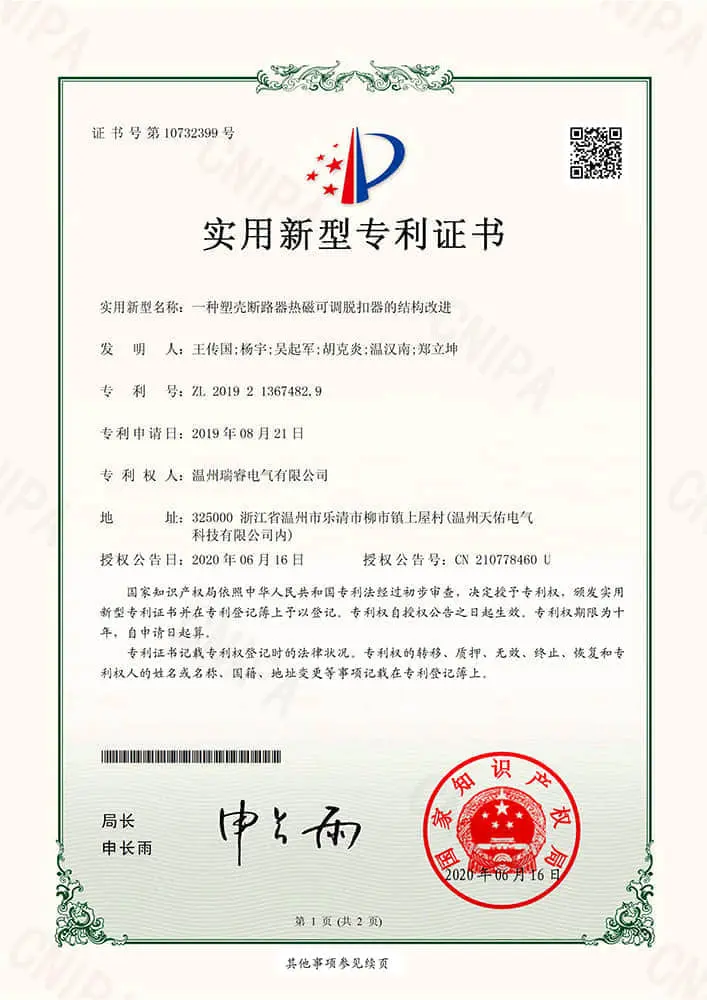
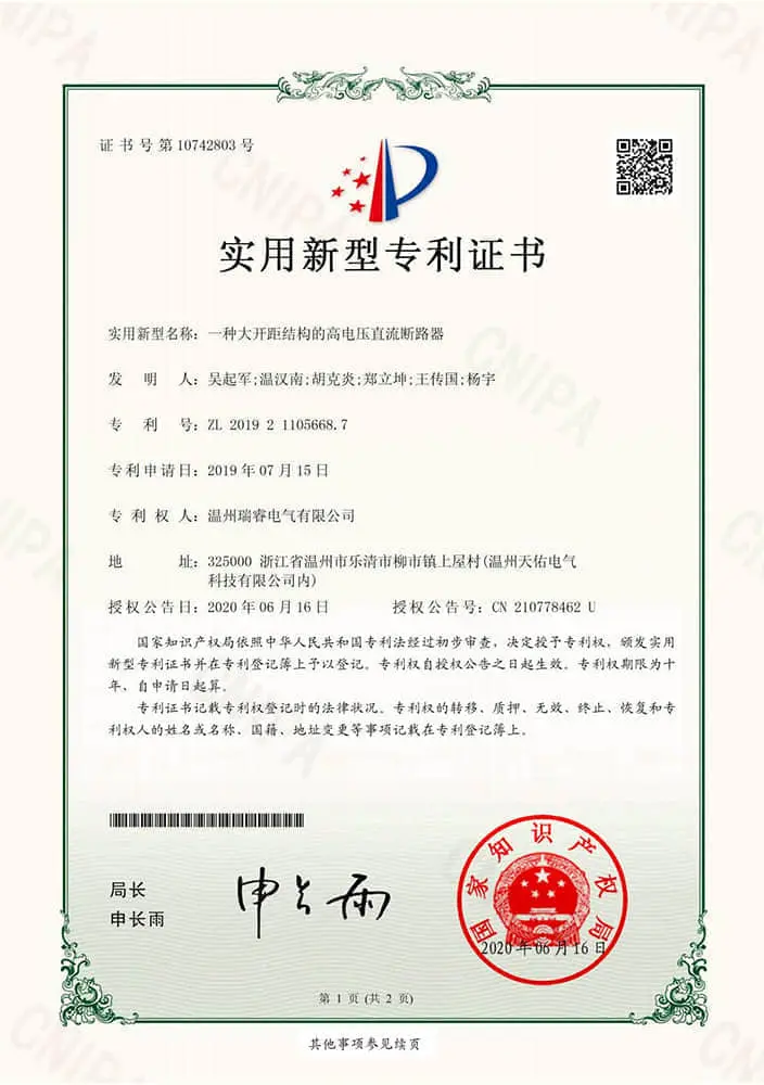
Answers to technical queries regarding secondary circuit integration and ACB sourcing.
 AceReare